Designing the Future: PCB, 3D Model, and Final Assembly
Published on: July 1, 2025
From Prototype to Product
With our breadboard prototype proven, May 2025 saw us dive into the sophisticated world of PCB (Printed Circuit Board) designing and 3D model designing. This phase was about transforming our functional prototype into a compact, robust, and aesthetically pleasing satellite unit.
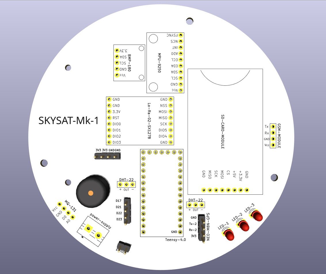
The brain of our satellite: Our custom-designed Printed Circuit Board.
We meticulously designed the PCB, considering component placement, signal integrity, and power distribution to ensure optimal performance in a constrained space. Simultaneously, our 3D model took shape, focusing on material selection and thermal management.
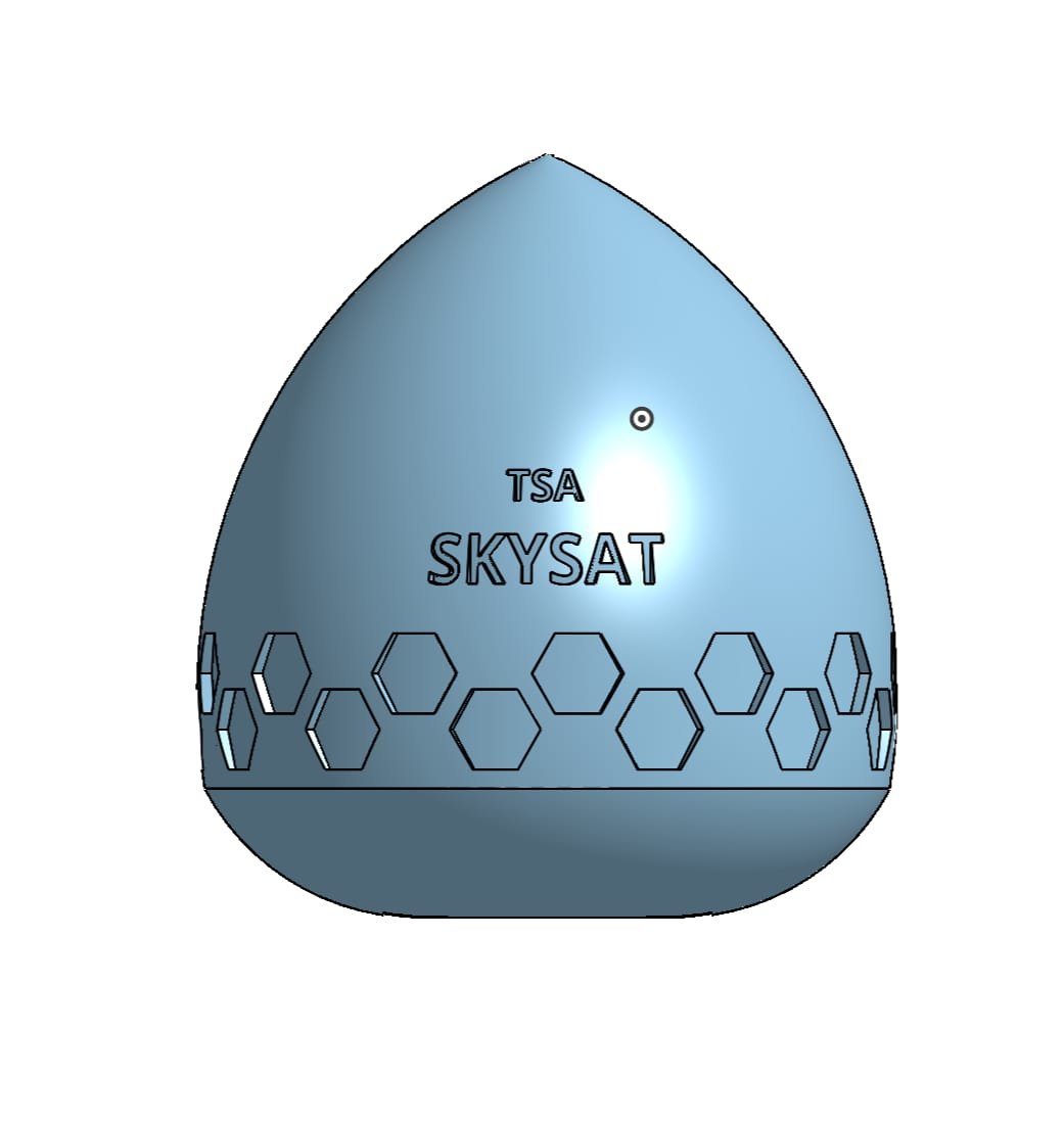
Bringing our vision to life in three dimensions!
From June 2025 to the present, our focus has been dual-pronged. We've been tirelessly conducting communication range testing with advanced encoding and decoding methods. In parallel, our workbench has been busy with PCB testing and the meticulous assembly of all components. We are on the cusp of bringing our satellite monitoring system to life!